4.5. Board Cutout
To cut the PCB to the desired shape and remove it from a larger blank PCB, a tool path that traces the board edge can be created. Gaps to hold the board until the job is complete can be placed along the edge.
This tutorial describes how to create rectangular cutouts with 2 or 4 gaps.
Open a Gerber file and find the Board Cutout section in the Selected tab.
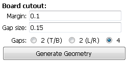
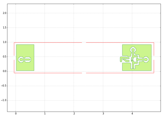
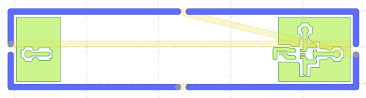
Specify a Margin. This will create a rectangular cutout at the given distance from any element in the Gerber. Specify a Gap Size. 2 times the diameter of the tool you will use for cutting is a good size. Specify how many and where you want the Gaps along the edge, 2 (top and bottom), 2 (left and right) or 4, one on each side. Click on Generate Geometry. The figure below shows an example of the results.
Create a CNC job for the newly created geometry as explained in earlier tutorials.
Note
Board cutouts of arbitrary shape and arbitrary number, location and size of gaps are possible. Visit the program’s web page for examples and tutorials.