4.6. Bed Flattening
Most often a sacrificial layer (e.g. wood) is used between the machine bed and the PCB so when drilling and cutting the machine is not hit by the tool. In order to have a completely flat surface for the PCB, the sacrificial layer is flattened by the machine. This tutorial shows how to create a tool path for this purpose.
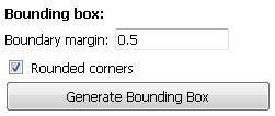
Open a Gerber file and locate the Bounding Box section in the Selected tab.
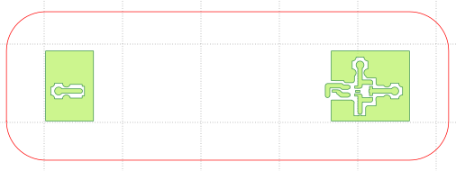
Specify a Margin (distance of the bounding box from any element in the Gerber) and whether you want rounded corners. Click Generate Bounding Box.
Make sure your blank PCB will fit in the bounding box.
In the Selected tab for the newly created geometry locate the Paint Area section. Specify the diameter of the tool you will use, how much (fraction of the tool width) each pass will overlap each other, and a Margin (although typically not needed and set to 0.0 in this case.)
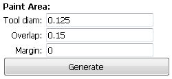
Click on Generate, and you will be asked to click inside the polygon inside which to create the tool path. Click inside the boundary we just created.
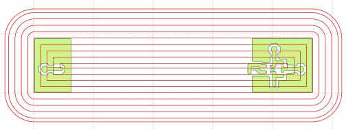
Create a CNC job for the newly created geometry as explained in earlier tutorials.
Note
Bed flattening of arbitrary shape are possible. Visit the program’s web page for examples and tutorials.