9.1. Eagle How-to
Quick guide on exporting PCB designs from Eagle and importing them into FlatCAM. This guide was made with Eagle version 7.2.0 Light and FlatCAM 8.2.
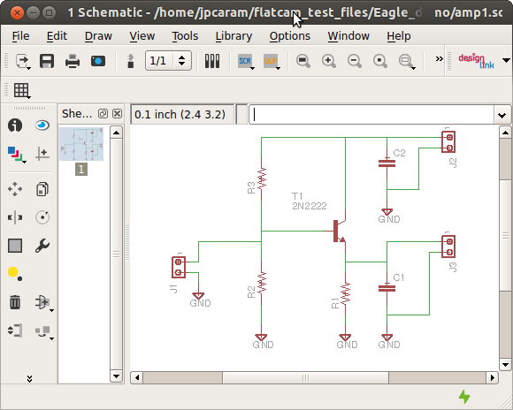
Most designs start with schematics of your circuit:
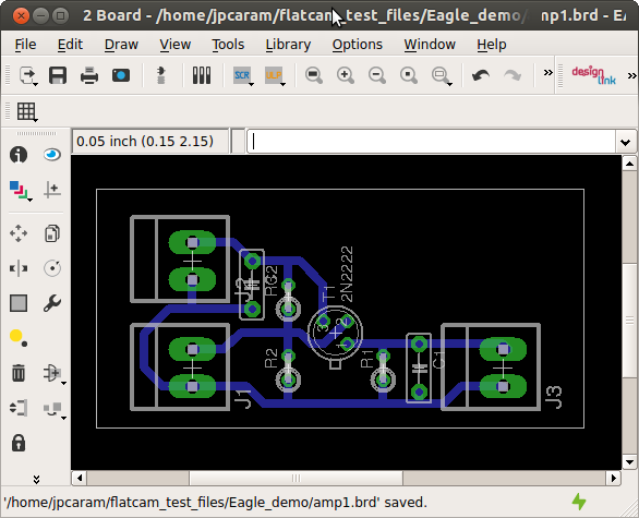
Then by clicking on File→Switch to board, the board editor is opened and you can complete your layout:
To export Gerbers, go to File→CAM Processor in the board editor, and choose the settings shown in the figure below. Include the copper layer that you want to export and the Pads and Vias layers. Choose a proper name for your output file and click Process Job. Repeat for each desired layer.
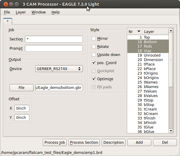
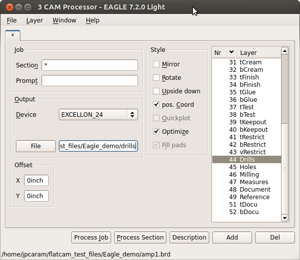
For drill files, go to File→CAM Processor again and select the settings in the figure below. Do not provide an extension to the drill file name. Click on Process Job to export.
We are done with Eagle. Now let’s move on to FlatCAM.
Eagle uses Trailing Zeros in its Excellon number format but does not properly report this format in the Excellon file. To tell FlatCAM to use this format by default set this system option excellon_zeros to T by using the set_sys command in the Shell Command Line Interface as shown below:
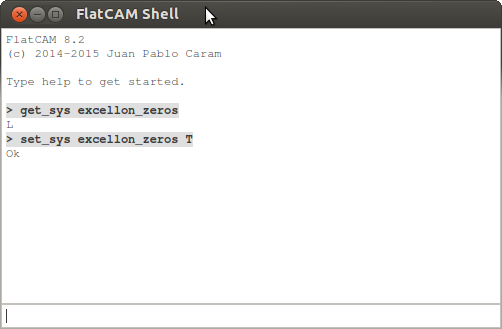
The command get_sys excellon_zeros is optional and only lets you
see what the excellon_zeros option was set to originally.
Note
Changes to system options are persistent. They will remain set to the given value when you restart.
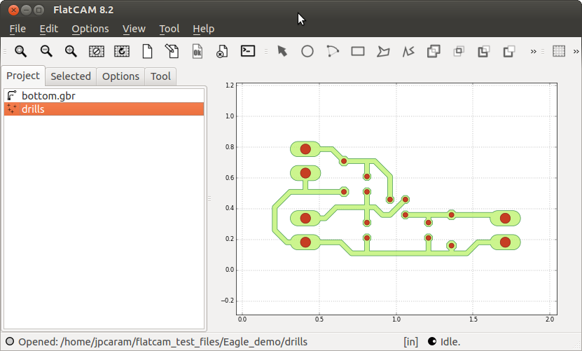
This completes all the adjustments. Now simply open the Gerbers and Excellon files that you exported from Eagle.