4.3. 2-side PCB
The main idea behind this process is to ensure that when you turn your board around to mill the bottom side of your PCB it will be perfectly aligned with the top side.
The mechanical alignment is accomplished by using alignment holes/pins. These are holes on your board and on the milling machine bed (typically a board of wood, known as “sacrificial” layer). Pins are used to align the holes on the board to the holes on the sacrificial layer. The holes are always pairs of holes that are symmetrical about a mirror axis. This ensures that when you turn your board around, the board can be aligned using the same alignment holes as before.
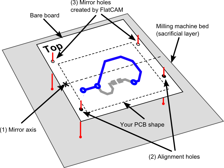
The bottom layer must be flipped (mirrored) around the same axis that was used for the alignment holes.
The placement of the mirror axis can be totally arbitrary. You just need to make sure that after flipping the board around, it will still fit on the milling machine bed. Same for the alignment holes. It doesn’t matter much where you put them. Perhaps if you have a large bare copper board and you plan on reusing the alignment holes for different projects that will be made out of this same bare board, you might want to define the location of the axis and holes, and record them for later use.
FlatCAM takes care of the rest. To ensure the symmetry of the alignment holes, FlatCAM asks you to specify the holes on only one side of the mirror axis and it will create the mirror copies for you. It will also mirror the bottom (Gerber) layer around the same axis.
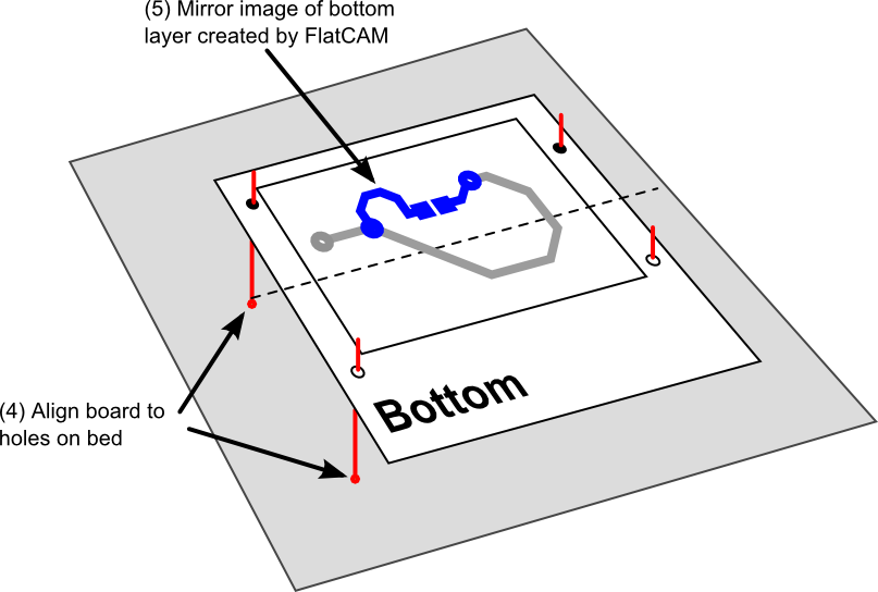
The process of making the double-sided board consists of creating the CNC Job Object for the top layer, the mirrored bottom layer and the alignment holes using FlatCAM. Then you can run the alignment holes job (you must drill through the board and into the sacrificial layer) and the top layer job. You must then turn the board around, align it using the alignment holes (fit some kind of pin in the holes) and run the bottom layer job.
Here is how to use FlatCAM to generate the required files:
- Open the Gerber files for the top and bottom layers of your PCB.
- Start the Double-sided PCB T by selecting Tools→Double-sided PCB tool.
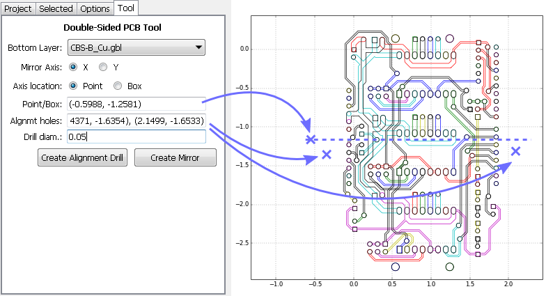
The tool has the following options:
Bottom Layer: Indicates which layer is the bottom layer, which needs to be flipped.
Mirror axis: Around which axis, X or Y, we want to mirror the layer.
Axis location: How we want to specify the location of the axis.
Point/Box: Specifies the location of the axis. It depends on the Axis location setting:
- Point: A single point specifies where the axis is, and you input the
coordinates of the point in the format (x, y). For example, if Mirror
Axis is set to X and Point is set to
(1.0, -1.0)the axis will be horizontal at \(y=-1.0\) (The x coordinate is ignored). - Box: If you have already defined the boundary of your PCB you may want the axis to be exactly in the middle of that rectangle. The boundary must be some geometry object defined in the project and can be selected in the combo box appearing in the Point/Box field.
- Point: A single point specifies where the axis is, and you input the
coordinates of the point in the format (x, y). For example, if Mirror
Axis is set to X and Point is set to
Alignment holes: These can aid in placing the board at the exact position after turning it over for the bottom side job. These holes must be symmetrical to the mirror axis. You only need to specify the location of the holes on one side of the mirror axis and the program will create the mirror copy. Input the coordinates of the holes in the following format:
(x1, y1), (x2, y2), etc.Drill diameter: The diameter of the drill for the alignment holes.
Note
You don’t have to manually type coordinates of points. Clicking on the plot
automatically copies the coordinates to the clipboard in (x, y) format and
these can be pasted into the input boxes.
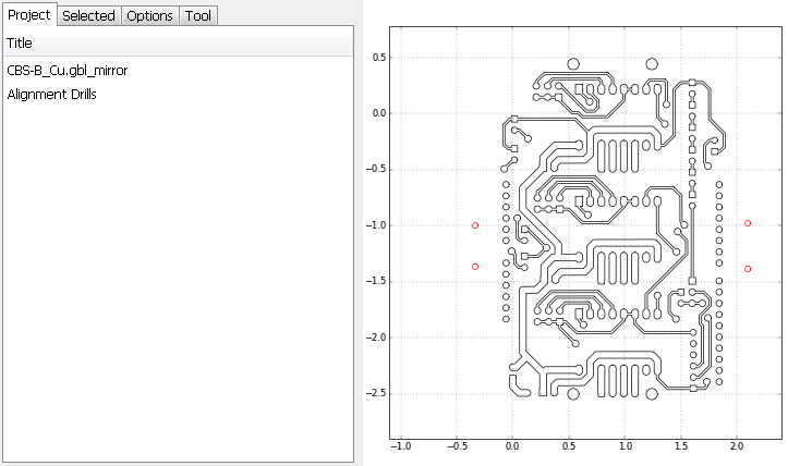
- Create the mirror image of the bottom layer by clicking on Create Mirror. This will create a new Gerber object for the project. You can work with this object, create isolation routing and a CNC job as it has been show in the previous tutorials. You may want to hide or remove the layer for the top side to ease the visualization.
- Create the alignment hole drill object by going back to the Double-sided PCB tool and clicking Create alignment drill. This will create an Excellon Object (drill job) as specified and a CNC Job Object can be created for it as has been shown for the previous examples.