4.1. Isolation Routing
Isolation routing is the operation of cutting copper around traces for electrical isolation. For details see the Isolation Routing section in the Gerber Object reference.
4.1.1. Single tool-width isolation
- Open a Gerber file: File→Open Gerber…
The file is automatically analyzed, processed and plotted.
Enter the diameter of the tool you will use for isolation routing and hit “Generate Geometry”. The units are determined by the project setting and are shown on the bottom right of the screen. If you want to work using different units, go to Options, Project Options (Combo box), Units. This will change the units for the whole project.
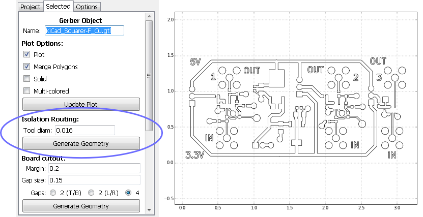
This creates a new geometry object listed under “Project” with the same name as the Gerber object with an “_iso” postfix, and its options are shown in “Selected”. Zoom into the plot (click over the plot and use the
2and3keys to zoom in and out) to inspect the results.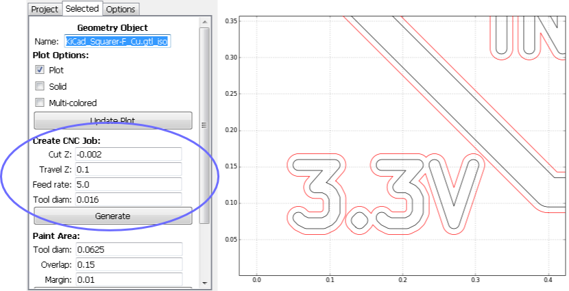
Create a CNC job from the new geometry by indicating the desired parameters as shown in the figure above and explained below:
- Cut Z: The depth of the tool while cutting. -2 mils or -0.05 mm are a typical value for isolation routing.
- Travel Z: The height above the board at which the cutting tool will travel when not cutting copper.
- Feedrate: The speed of the cutting tool while cutting in inches/minute of mm/minute depending on the project settings.
- Tool diam.: The cutting tool diameter. Use the same value as when creating the isolation routing geometry in step 2.
A CNC Job object has been added to your project and its options are shown in the “Selected” tab. Tool paths are shown on the plot. Blue are copper cuts, while yellow are travelling (no cutting) motions.
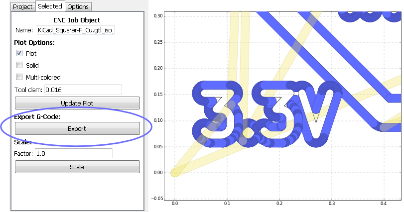
Click on the “Export” button under “Export G-Code”. This will open a dialog box for you to save to a file. This is the file that you will supply to your CNC router.
4.1.2. Wide Isolation Routing
Note
This description is obsolete. In the current version of FlatCAM, isolation routing with multiple tool width is automatically calculated.
- Go to the Project tab and double-click on the isolation geometry object that you created for the 1st pass. In the Selected tab, change its name and hit Enter.
- Go back to Project and double-click on the Gerber object. This takes you back
to step 1 of tutorial 4.1. We will generate geometry for a second pass in the same
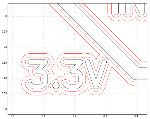
way but with a larger offset. If Tool diam reads
0.016, enter0.016*2.5instead (0.016*3would put the path 3 times as far which provides no overlap with the previous pass. By setting it to0.016*2.5you ensure that there is no copper left on the board and a cleaner finish). Click on Generate Geometry just like in tutorial 4.1 and you should get something like the figure below.
- Generate a CNC job like you did in part 3 of tutorial 4.1. You will end up with 2 G-Code files, one for each pass.